Friday, October 11, 2013

Rostock Delta Robot- Electronics

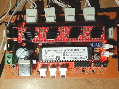
Assembling the electronics for the Rostock Delta has been achieved with far more ease than any of the other printers I've constructed. The physical design of the printer has much to do with this.

By having all three stepper motors located in close proximity of the Arduino/RAMPS controller, the wiring is  routed more efficiently.


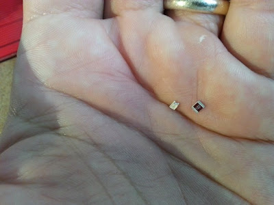
Placing the end stops has been the confusing part. I haven't found any clear information on the placement, and I'm still not sure if I need six or only the three I placed. I'll determine this when I setup the firmware and make the physical calibrations.


The heat bed was simple. There isn't the usual setup of screws and springs. I'm not sure how the leveling will be accomplished, but I’m sure that will also be clarified later.


 I added a 1/4" foam core barrier between the wood base and the heat plate. This should allow for insulation and also enough of an offset allowing for the attachment of a glass plate with clips.


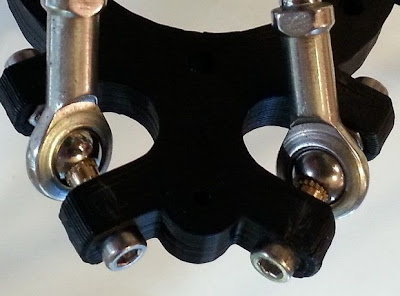
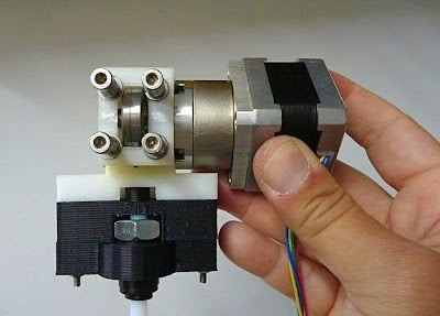
I’m using the old extruder design from my RepRapPro Mendel. It mounts beautifully on the side and allows for perfect positioning of the Bowden cable and the filament feed.


The hot end is the E3D-v5 1.75mm filament version. I downloaded the parts for the mount at thingiverse.com (thing:80616). With a few minor modifications, I made it work. I wanted to be sure the hot end was easily removed with its cabling and Bowden tube, so any future repairs can be made with ease.


Up next, will be software setup and calibration.


Thursday, August 22, 2013

Rostock Delta Robot- Mechanics

Building the Rostock Delta is important for me for a number of reasons:

  • First, the simplicity of the design. Eventually, if all goes well, I’ll need to build larger machines. This design may prove to be the easiest route to take.
  • Second,  I plan to experiment with faster printing speeds and faster printing speeds with larger nozzle sizes. The Rostock boasts a positioning speed of 800 mm/s in all three directions. 
  • Third, the manner in which the electronics and stepper motors are shielded from the printer mechanics seem optimal for creating a temperature controlled chamber.
  • Fourth, the bed remains stationary. This will be very important when I’m prepared to set up a system for clay extrusion. I’m certain that with the typical RepRap printer the motion of a build platform while extruding clay (especially large models) would become problematic. The Delta design will eliminate this situation.


Overall, the mechanical construction of the Rostock Delta has been the easiest of all the printers I have built. One of the major factors for this ease has been the wood support components. I downloaded dxf files of the wood members (thing:34570) and simplified the design by eliminating the intricate “crown shape” cuts which allow fastening by screw and nut. I then had a local sign shop CNC router the pieces out of MDO. This obviously provided me with perfect angles and drilled holes for the placement of plastic parts I printed on my Mendel Prusa (thing:17175).

I couldn’t find specific assembly instructions for this printer, except for the Bill of Materials list (referenced by the RepRap Rostock Wiki). I think, with some previous knowledge of a RepRap build, it’s easy to figure out.

I made a choice early on to upgrade the printed arms with bearing arms and set screws that I purchased on eBay.

 This was a very good move on my part. The fluid mobility of the joints are superb.


I also equipped the stepper motors with 40 tooth GT2 plastic pulleys rather than the 8 and 20 tooth aluminum pulleys that I’m using on my other printers. This may or not be better. The original specs for the Rostock called for the 40 tooth pulley. I've later discovered since purchasing the GT2's, that they'll  have less torque and a lower resolution than smaller pulleys. On the upswing, the GT2 belts and pulleys are designed for linear motion and this will eliminate the backlash which my T2.5 and T5 pulleys are prone to exhibit.


Overall, a very sturdy design. I’m looking forward to getting it moving.


Sunday, August 18, 2013

The E3D-v5 HotEnd and bowden cable system

The E3D-v5 HotEnd from e3d-online.com is a new hotend that I’m interested in trying. It has an all metal construction (without the use of PEEK) which gives it the advantage of operating at higher temperatures.


This is important since the nylon and polycarbonate filament that’s become available requires much higher extruding temperatures.

The hotend is sold as a kit which consists of a handful of parts that are very easy to assemble. There are two design features I’d like to point out.

First, the hotend utilizes a robust ceramic resistor that's held in place by a small allen screw.


Second, the thermistor has a very nice cavity to plug into and then wrap around and through the block which provides a good anchor.


I purchased this hotend with the additional bowden cable accessory. I could have devised a bowden system from scratch, but this hotend has a coupler which screws nicely into the end. It's a nice system, but I still had to  fabricate a part to clamp it to the x carriage.

Using OpenSCAD, I redesigned the bowden mount available on https://github.com/MakerGear/MakerGear-Prusa-Mendel and designed a mount clamp on SketchUp.


The OpenSCAD file was also modified so that the bowden cable coupler could be used with the  MakerGear Brutsruder. This also required adding a M8 nut.


The bowden system is quite adaptable. By using 2 M8 nuts on each end of the couplers, I'm able to attach a MakerGear hotend and use it on my Mendel Prusa.


Sunday, August 11, 2013

Printrbot Commissioning

I've completed my Printrbot's mechanical and electronic systems and now I need to tweak the programming and software for operational control of the printer. This requires a little more work with a Sanguinololu board than what's required with an Arduino based controller.

In order to load the firmware on the Sanguinololu, I had to first install a Virtual Com Port USB driver from http://www.ftdichip.com/Drivers/VCP.htm. I then plugged my Sanguinololu into a USB port and directed the Detected New Hardware prompt to the CDM driver folder. Once a port was established, my Sanguino was recognized by Windows.

Next, I needed to download a pre 1.0 version of Arduino software. I'm using 0023 and it can be found here http://arduino.cc/en/Main/Software. The Arduino program needs to be set up with some new files and a modified avrdude.conf file. I downloaded Sanguino1284p-master.zip from here https://github.com/jmgiacalone/sanguino1284p. I added the contents to the hardware folder of arduino-0023. Allow Windows to merge the tools folder and overwrite the avrdude.conf file. Now the Arduino software will recognize the Sanguino.

Next, I needed an updated version of Marlin firmware. I downloaded Marlin-Marlin_v1 from here https://github.com/ErikZalm/Marlin.

Next I needed to edit the Marlin firmware with the Arduino software. I opened the Configuration.h file and first changed the electronics board setup from the default:
#define MOTHERBOARD 33
to:
#define MOTHERBOARD 62

Next I had to get my mechanical settings corrected specifically for my Printrbot.
Under:
 // Endstop Settings
I changed the default values “true” to "false" in these 3 lines:
const bool X_ENDSTOPS_INVERTING = false;
const bool y_ENDSTOPS_INVERTING = false;
const bool Z_ENDSTOPS_INVERTING = false;
Under:
// Disable axis when it’s not being used.
I changed the default values "true" to "false" in the first 2 lines:
#define DISABLE_X false
#define DISABLE_Y false
I also changed the build volume to Printrbot size:
#define X_MAX_Length 100
#define Y_MAX_Length 100
#define Z_MAX_Length 80

Next, in order for the new fan circuit to be operative, a change needed to be made in the pins.h tab.
Under:
 *Sanguinololu pin assignment
I changed the default value -1 to:
#define FAN_PIN   4

Of course, the usual changes need to be made to the movement settings in the firmware during calibration. Finally, the edited Marlin firmware can be uploaded to the Sanguinololu.

I'm using Printrun as a host. There’s a few things to do here as well. Under Options from the Settings menu, I changed the build_ dimensions to 100x100x80. I then selected the correct port for my USB connection and set the baudrate to match my firmware.

For my first test runs, I used PLA filament and Slic3r. Slic3r has better fan control options and since this is my first printer equipped with a fan, I’d like to test the system more throughly. I used the 5mm cube steps pyramid calibration test (thing:56003) for my first run.


The fan cooling system certainly works very well for areas which are usually more difficult to print without the additional cooling.


Next, I ran some bridging tests. I made a 25x25mm open cube.


There is the slightest hint of one drooping strand on the print and several others that were printed.


Last, I ran a bridging test using the bridge torture test (thing:12925). This model requires a span of 50mm to be printed from 2 posts.


With some tweaking of the slicer options, A successful print was made.

Monday, July 22, 2013

Printrbot Electronics

For the Printrbot I've decided to use a Sanguinololu v.1.3a controller. It’s equipped with the ATMEGA 1284 chip and Pololu driver clones.


The primary reason for this setup and not an Arduino Mega with RAMPS shield is because there isn’t much room to place all the components under the print bed. The Sanguinololu is a slim all-in-one unit (minus the drivers).


I added a 4.5" x 6" PCB heat bed.


For the LED indictor I  used SMD components.


 Because of their tiny size, it’s not exactly the greatest choice when a soldering iron is the only tool I have, but I found that by adding a little solder flux and adding little mounds of solder to the board connections first is the easiest way to accomplish this. Placing the components next and then heating the connectors with the fine tip of an iron will remelt the solder underneath and make a good bond.


For this printer, I’d like to use a PWM fan. This is a fan that uses pulse-width modulation to control it's speed. Since I plan to be printing with a lot of bridging techniques that may require G-code implemented cooling procedures using a fan, this is a necessity. Unfortunately, the Sanguinololu doesn’t have the required hookup for a PMW fan. To get around this, a separate circuit must be made. I used the circuit outlined here www.thingiverse.com/thing:22202. I did make some changes:  I eliminated the 0.1uF capacitor and swapped out the RF540A MOSFET with a STP55NF06L MOSFET. This is the same MOSFET that’s used on the RAMPS board and is sufficient for use here as well.


This is the first 3D printer replication that I've made. All the plastic parts were made on my Prusa Mendel with some minor parts made with the RepRapPro.


In order to make the electronics work with my preferred host (Printrun) some changes will have to be made in the firmware. This’ll be covered in the next post.

Sunday, June 30, 2013

Printrbot Mechanics


This next printer build is necessary for an on going project and also it’s to act as a dedicated printer for future clay extrusion experimentation. I plan to highlight the assembly and make note of anything interesting as I move through the building process.

All of the parts were printed with my RepRapPro Mendel.


 I purchased the LM8UU bearings from an eBay seller and as the saying goes, you get what you pay for. I paid $5.27 USD for 10 bearings and got a poorly manufactured product. The tiny ball bearings pop out if extreme care isn’t taken. They still work, but I’m not sure if I’m getting a smoother ride than printed PLA bushings.


The base is a solid design and is easily leveled.


I found a lot of 5 used NEMA stepper motors with T2.5 pulleys on eBay. The shafts are short, but work well for the Y and Z axes.


I used a clear acrylic sheet for the bed. The only major design change I made was with the Z axis threaded rods. I swapped out the 5/16" rods with 1/4" rods. A similar feature of the RepRapPro Mendel.


There were a few problems which had to be solved to adjust the X axis carriage. I had a difficult time in lining the 2 bearings parallel on the X axis rods. I ended up cutting out the bottom end of the carriage and zip tying the bottom bearing in place.


I’m using an accessible Wades extruder that I made on my first printer. I switched out the hobbed bolt with the Arcol hobbed bar, Hyena 1.0.


Overall, the mechanical assembly was easy and much faster than a Mendel printer design.


Addendum 22July2013

Getting the mechanical functions tuned to perfection has been a pain. This has been primary due to imperfections in the printing of the plastic parts. I originally printed them in gray ABS on my RepRapPro Mendel, but they’re not working out. I'm not getting good prints because the X and Y belts on the  RepRapPro are slipping. This I plan to rectify once and for all which I’ll cover as an addendum to my last RepRapPro post. For now, I reprinted the parts in black ABS on my Prusa Mendel.

Next, the low grade LM8UU bearings have been replaced with better bearings. I think the cheap ones would probably be fine, but I prefer to keep the performance higher on this printer.

Next, I decided to ditch the Wades extruder and go with  the MakerGear Brutstruder and hot end. I have tested this system time and time again with no problems and I prefer to keep with what works. However, I did print the Brutstruder parts and assemble the hot end to be fed with 1.75 filament. I really believe that 3mm is better, but for the purposes of an on going project, I’ve made this decision.

Last, I decided to add the components needed for a fan. I printed the fan system designed by erossman and posted on www.thingiverse.com (thing:32605). I cut out the ducting which cools the hot end with some snips to give the nozzle full usage of the air.

Wednesday, June 19, 2013

RepRapPro Mendel (part 7)

The RepRapPro Mendel has been a great printer, but it’s been plagued by a number of issues which arise from prolonged print runs and constant use. This, I believe, is not indicative of an inferior machine, but just the nature of DIY printers in general.

This entry will survey more of the problems I’ve had with the RepRapPro Mendel. Some of these problems must be prevalent with their printers at large since RepRapPro has made some recent design changes to correct them. Most of these problems, I’ve had to solve on my own.

Here are my recent issues:

I’ve had problems with the parts which are exposed to the heat of the bed. This is probably because the parts are made with PLA rather than ABS. PLA has a lower tolerance for heat.

The Y belt clamp has been a continual headache. The heat from the bed softens the clamps and this causes the belt to slip. The screws are instrumental in this problem by conducting too much heat through the clamp. I’ve had to make several adjustments or modifications to keep the belt properly tensioned.


The Y axis motor mount has warped considerably over time and had to be reprinted. RepRapPro now sends this out as a laser cut wood part in their kits. I remade the part in ABS which should hold up fine for my use.


The next problem I’ve had is with the bowden cable attachment at the extruder side. The clip which holds it in place would wiggle its way out and the cable would detach. I lost several long print runs because of this. I fixed it by simply tying the clip in place with a zip tie.


The next problem is with the Melzi controller. I just haven’t had much luck with this board. This time it's with the mini USB connector. It separated from the PC board. Fortunately it wasn’t damaged and I could solder it back in place, but it wasn’t a very easy task to accomplish. The 5 pins are very small and it  required some very steady work and I think some luck to get it in place.


The last problem has been a reoccurring failure of the heat resistor, but RepRapPro has made a component change and now sells a more robust ceramic heat resistor. The replacement part I found as a substitute has been easier to install, but hasn’t provided any longer service than the OEM part. I’ve purchased replacements for all my RepRapPro hot ends with the new ceramic resistor.


Once again, I think the RepRapPro Mendel is a great machine and I would recommend it highly to anyone who is looking to purchase their first printer. It’s a very nice system and it’s continually improved.

There are just inherent weaknesses in the DIY system. I hope that by finding these weaknesses in all of my printers, I’ll be able to perfect the technology for my use in creating sculpture. This has been my underlying rationale for building the printers I have so far.

Addendum Aug. 18, 2013

I can't seem to keep the belts on my XY axes tight. My best solution was to drill holes in the X carriage and run the belts through them and then clamp with nylon ties.

 I did this also for the bed.


I also had a problem with one of the PLA printed pulleys. I replaced both XY pulleys with aluminum T2.5's that I found on eBay. Since the pulley diameter is larger than the OEM versions, I had to re-calibrate the axes.